Keyboard DIY
News Reviews How-To's
This is the MX HHKB kit that will be built in the guide. I got the black version and will be using Gateron Green switches for this one. Most kits include everything you need to make the build, but make sure you have the switch plate, case, pcb, switches, screws and stabilizers. Optional items are leds and sip sockets.
Note: If you are planning on adding sip sockets, not all plates are support switchtop removal. If it doesn't, you will have to add the sips sockets to the switch before adding them to the plate. Example of switchtop compatible and switchtop incompatible.
PCB Keyboard Build Guide
Prep
I test the PCB before doing any soldering. There are some vendors that will not allow you to return a PCB after it has been soldered and it would really suck if you built the whole board to learn that some parts are faulty. In order to test switches: plug in the PCB, load up your keyboard tester and use some tweezers to short/activate each switch. Once everything checks out, you are ready to start building!
I like to start with the stabilizers, personally. These are Cherry-style stabilizers, and this kit comes with the clear version, apparently. This will be my first time working with the clear ones.
Here we can see the underside of the PCB. Like a lot of PCBs on the market these days, this one comes with all of the little parts pre-soldered: diodes, resistors, controller and USB port. Way less work for us, because that would easily add several hours to this build process.
This is the correct orientation, by the way. The side with two holes on the smaller piece is the side that faces the back of the stabilizer, where the wire will later be inserted. The design of these is actually a little different than the more traditional Cherry PCB-mount stabilizer, but it's assembled and functions the same way. (Left pic)
Here is a better look at that specific side. This piece is inserted into the larger piece via the bottom, and then the stabilizer wire will go in the bottom of the two holes, then clip into the back of the stabilizer (on the larger piece). (Right pic)
Now we can prepare the switches! The switches I have are PCB-mount switches (they have 2 extra plastic legs for stability). Since we have a plate in this build, we're going to cut off the two extra plastic legs with some flush cutters. PCB mount switches without the 2 plastic support lets = Plate Mount. Do note, you can't go the other way around.
So, at each stabilizer points on the PCB, there will be two larger holes (marked in black here), where the back of the stabilizer will just slide in and under the PCB a bit, and two smaller holes (marked in red here) where you will need to push the pin section of the front of the stabilizer into the PCB. It might take a little force, but it will be okay.
Woot, it's in! Do note that while this stabilizer orientation is correct for this spot (left shift), that doesn't mean the rest of the board will be like this. Fortunately, the holes will make it easy to see which way they go. The back slides into the bigger holes, and the pin slides into the smaller holes. ;)
Here is an example of that. Notice the left shift has the wire facing down, while the wires on the other two stabilizers face up. Orientation isn't really consistent across PCBs, so just install them the only way your PCB allows you to. Anyways, they're installed! Notice this board, because of the HHKB-styled layout, only uses a total of three stabilizers, while a standard 60%-styled board or TKL would use 5. full-sized boards use even more. Now is also a good time to test the stabilizers. They should pull up very easily and fall right back down if let go.
Anyways, here is the bottom of a switch. Notice the little plastic legs on either side? Those are to provide extra stability to the switch, if you're mounting them directly into a PCB without a plate. Since we are using a plate, we do not need these. You could leave them on if you wanted, even with a plate, but pushing them into the PCB while also using a plate is incredibly annoying, and you get no benefit from it anyways, since the plate is going to provide the stability for us!
Here is one I just clipped the legs off of. Be careful not to accidentally cut the metal contact pins or the center pin, as we still need all of that. This one isn't the best example, but try to snip as close to the base as you can. Some people like to file it down even further after clipping, more better aesthetics, but since we won't ever be seeing this part and I'm not a perfectionist, I don't care enough to spend the extra time for that. Caution: the little pins you're clipping will fly....EVERYWHERE.
As you're sorting through your switches, chances are you will comes across one (or several, probably) switches with a bent metal contact pin. Don't worry, this isn't a big deal. It happens all the time and it's quite easy to correct. Just gently bend it back with your finger(s), knife, tweezers, etc.
Once you're done clipping legs and correcting pins, line up the PCB and plate and push in a switch at each corner. It might be kind of annoying at first, but it will get easier, trust me. We're going to solder these corner switches in first, so it provides some integrity while we push the rest of the switches in.
I typically solder at 350c. I hold the iron to the pad for a second or two, to heat it up, then I apply the solder. You will usually need to touch the solder to the tip of the iron very briefly, to get the solder flowing. then slowly push the solder in. I like to end with a nice little Hershey kisses just large enough to cover the pad. Each pin (not switch) takes me about 3-4 seconds to solder, if I'm being careful. If you hold the iron to the pad too long, you risk lifting the pad, and that's not good. Also, be careful not to over-apply the solder, too. You are looking for a some small peaks, not bubbles!
After I get all of the switches in, I double check each pad to make sure the switch pins are poking through. If you're missing one where it should be, that typically means you bent it while trying to press the switch into the plate/PCB. Just take it out, fix it, and try again. There are little nubs on the front and back of a switch, just above where it sits in the plate, when mounted. Push in each of those and gently pry up to remove the switch.
Alright, so about 15-20 minutes later, the board is soldered. Might take you a bit longer, if you're really new to it. Take as much time with it as you need to. You shouldn't ever feel rushed during a build. Set aside way more time than you think you'll need to do this. Notice all that nasty-lookin' stuff around the domes of solder? That's leftover flux residue. It's totally normal, and won't hurt anything. If you're a perfectionist, there is a flux removing spray that you can buy, and you just brush it off. You can also use a high percentage isopropyl alcohol, but it might take a bit longer.
Now that we have all the switches soldered, let's check to make sure they work, as well as the LEDs for the underglow. Just plug it in and load up your keyboard tester to make sure that each switch is activating. If everything checks out, you are ready to assemble the rest of the board and close shop!


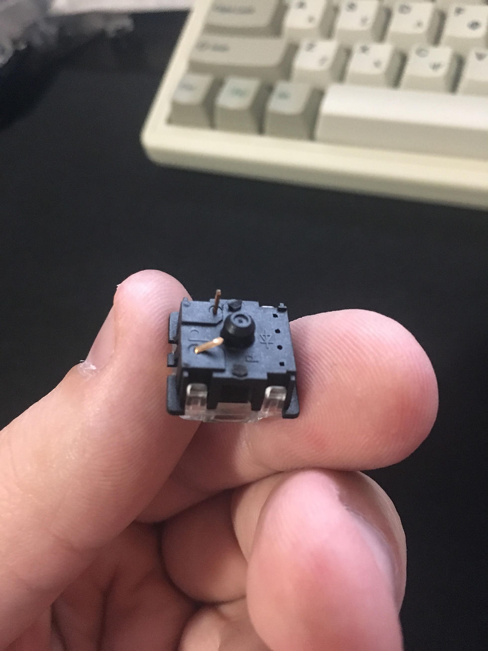
Don't get bent out of shape! Just gently straighten it.
Soldering Switches


Adding Leds
I normally don't add leds to my build, but if you want to here is a tiny guide. I would only recommend using leds that are 1.8mm or 2x3x4, since 3mm leds can have issues with keycap clearance. Set up your keyboard so it's backlighting is activated and the switches/PCB are exposed. Take your leds and drop them into the switches (green circle) and orient it so the longer leg is going through the + side. *If there is no marking on the PCB, you can use trial and error for the first one so you know how to orient all of the others.
I test all my leds before soldering them in, since desoldering leds can be a painful process. Give the two legs a squeeze and they should light up. Repeat for all of them and replace non operational ones. Unplug your keyboard and you can solder the leds in with the same process you did with your switches.
Big shoutout to /u/quakemz for the writeup.
In order to compete a keyboard build, you will need to the following components:
-Switches
-Stabilizers
-PCB
-Plate (optional but recommended)
-Case
-Hardware/screws to install case
-Keycaps
-Leds and Sip Sockets (optional)
*This is optional. There are plenty of people that prefer to keep the Legs in even thought they have a plate.*